You operate your mobile phone, a TV remote, even the Internet device you are using right now; they all involve some circuitry behind them. PCB (printed circuit board) is used for the circuit assembly. Here is a review to design different electronic components.
Starting with schematics
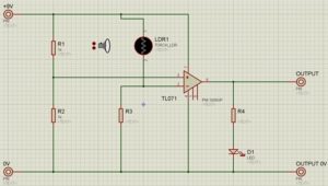
Right in the beginning, you need to know whether your circuit will work or not. So you need to run a simulation for your circuit and you need PCB design software. Different software’s are available like Proteus ISIS and PSpice are worth mentioning. Draw the schematics on your software and run to check its working conditions. You can also change the values of different components to obtain different results. given below the screenshot of Proteus ISIS Professional software.
A Glance at Printed Circuit Board (PCB)
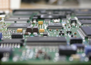
Most of the time, the circuit is built on a board. The board comprises of a circuit pattern. A PCB is made up of fiber glass with copper coating on one side. The circuit is printed on the PCB and the conduction path is completed through traces of copper. A PCB can be single layered or Multi-layered.
 Preparing the Board Layout
When you are done with schematics on the software, you can draw a PCB Layout on the software just like ARES provided by Proteus. These schematics are then transferred to PCB. Well there are different techniques either using a permanent ink marker or using software, but a professional method is to adopt software. Tutorials are available online to print schematics on PCB through heating, usually with an iron. After printing, PCB is put in a chemical, mostly FeCl3 for some time that leaves behind the traces of copper that were printed. The remaining ink spots are removed by using spirit or petrol. Now your PCB has the circuit on it that you wished to design.
Getting your PCB manufactured
When you circuit is done, it’s time to check the continuity of the circuit. You might use a DMM (digital multi meter) to do this. After checking continuity, now you have to make drills in the PCB where the components will be placed. A Perf board has already holes in it so it does not need to be drilled. After drilling , place the components where they are to be placed and apply patches using a soldering rod and soldering wire. Once the patches are complete, your PCB is ready to work. Connect the supply and run your circuit.
At Giltronics Associates our design team would like to partner up with you on new and existing projects to cut your manufacturing cost in the printed circuit board and electronics assembly. Our engineering team can design in new cost cutting materials and enhance the electronics to overcome your competitors. Please don’t wait give us a try. Contact us today!